Thomas & Middlecoff Controls -These controls are the explicit form for orthogonality. They are computed based on the defining faces of a block. Basically, these source terms produce volume grids with orthogonality on the interior and attempt to obtain orthogonality at the defining edges. Consider the grid shown below:

Thomas & Middlecoff Grid

This volume-grid plane shows the results of using the Thomas & Middlecoff source terms in solving Poisson's Equation for volume grid generation. Notice the interior does have some orthogonality, but the points near the edges do not.

Within 3DMAGGS, the Thomas & Middlecoff source terms may be used alone or in combination with the Sorenson & Steger source terms. The Sorenson & Steger source terms are implicitly computed and corrected iteratively until the first point away from a boundary is orthogonal to the boundary, as shown below:
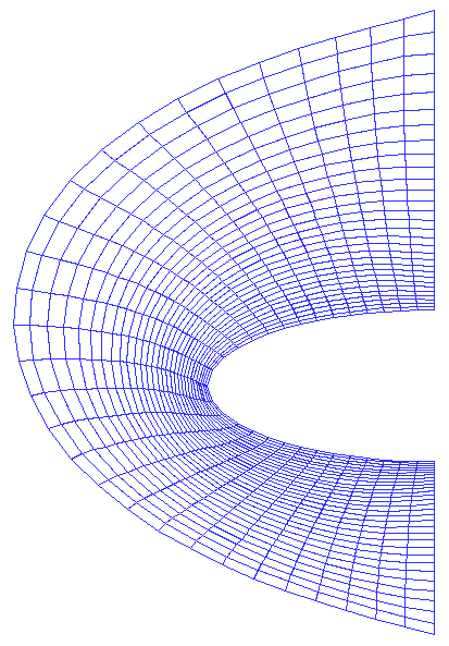
Steger & Sorenson Grid

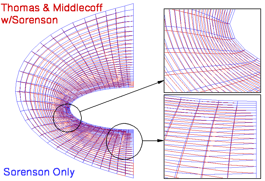
As stated above, the Thomas & Middlecoff source terms can be combined with the Sorenson & Steger source terms. This combination results in a grid with both orthogonality at the defining edges and near orthogonality on the interior of a volume grid. Shown below is the results of combining both types of source terms.

Steger & Sorenson and Thomas & Middlecoff Hybrid Grid

Typically, Thomas & Middlecoff source terms are used to improve the quality of grid lines extending from the surface of a vehicle to the outer boundary where the flow field in a CFD simulation is undisturbed by the vehicle. Though, Sorenson & Steger is the usual method employed for obtaining orthogonality in a volume grid, the addition of Thomas & Middlecoff can significantly improve the grid adaption process to simulated flow fields. The improvement comes from the increased straightness of grid lines from the surface of the vehicle and the outer boundary. Thus, the hybrid control functions (or source terms) of Sorenson & Steger and Thomas & Middlecoff offer better modeling of a flow field by enabling enhanced grid adaption.


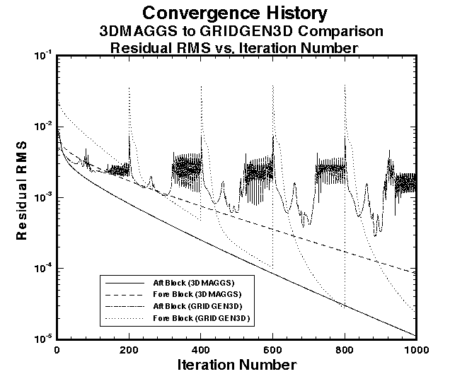
One of the more powererful features of 3DMAGGS is its ability to use optimum relaxation rates. These rates are based on the eigenvalues of the Poisson's equations used for elliptic volume grid generation. And, unlike GRIDGEN3D, the 3DMAGGS code has a true restart capability; the code can restart from where it left off, in an earlier computation. The GRIDGEN3D code attempts to determine the source terms from a given grid, resulting in loss of computing time for the elliptic solver. This can be seen in the "jumps" in grid-point-movement residuals in the plot below:

3DMAGGS & GridGen Grid Movement Convergence

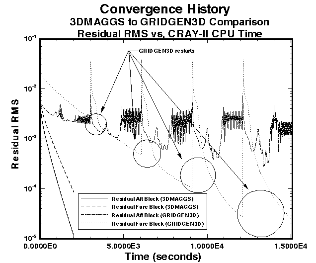
As stated before, the 3DMAGGS code can be an order of magnitude faster that GRIDGEN3D. The plot below shows a difference of 7.5 times, but notice the location of the residuals after 15,000 seconds of CRAY-II computing.

3DMAGGS out performs GridGen

The GRIDGEN3D code has not yet converged! The data presented above was generated from the volume generation of a
two block analytical shape .


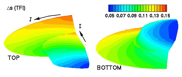
The only method GRIDGEN3D has to generate the cell heights used at a surface with the orthogonality boundary condition activated is the use of Trans-Finite Interpolation of the cell heights at the edges of the surface. But 3DMAGGS offers any cell size the user may want. There are 3 types:

1) A constant cell size.
2) A 9 point function in one index direction describing cell sizes.
3) Importing from an external source.

The PREMAGGS routine that is used to convert GRIDGEN3D input into 3DMAGGS input offers 4 different types of cell sizes for importing:

Blend between opposing faces in the I-direction:
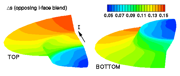
Opposing Face Interpolation; face 2 to 4

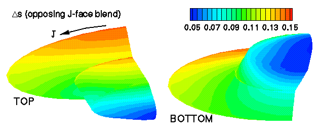
Blend between opposing faces in the J-direction:

Opposing Face Interpolation; face 1 to 3

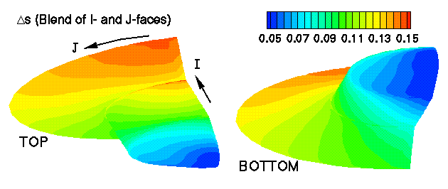
Blend between opposing faces in the I- and J-directions:

Local Arclength Cell Sizing (LARCS) Result

Modified TFI (correction terms omitted):

Modified Trans-Finite Interpolation (TFI) Result

Use of these various methods gives the user the option to choose or make up a cell sizing function for import into 3DMAGGS.


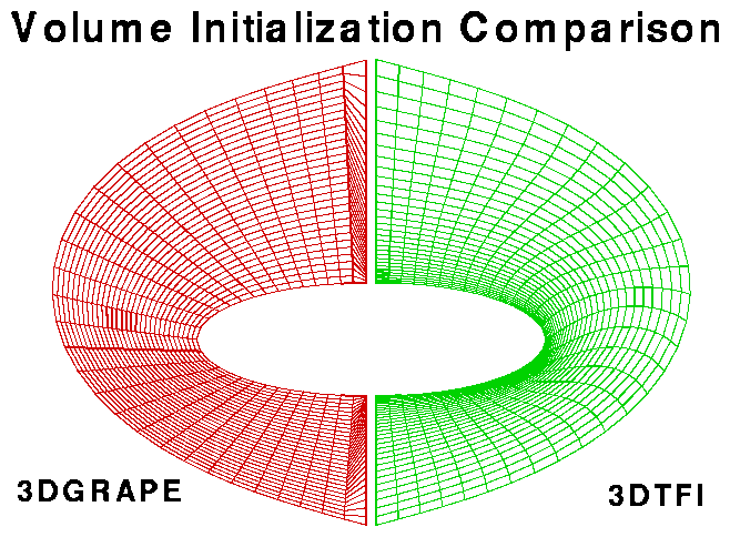
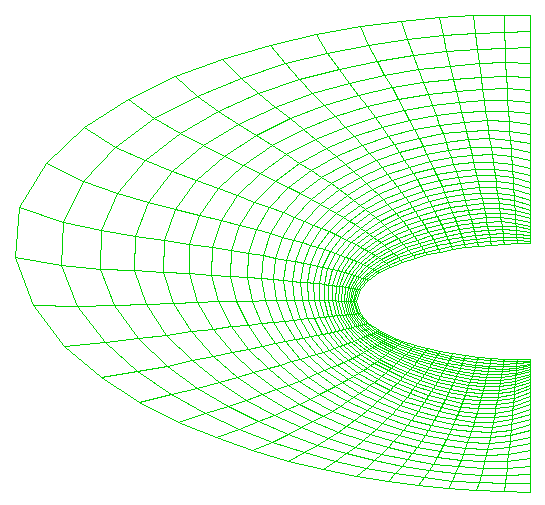
Three Dimensional Trans-Finite Interpolation - This type of interpolation can be used to generate the initial volume grid, instead of the straight line initialization of 3DGRAPE. The use of 3DTFI can significantly reduce the time to a converged grid, evident by lower grid point movements, due to the more applicable grid. From 3DTFI, a grid may not need extensive smoothing, as does the 3DGRAPE initialization. Below is a cross-section from one plane interior to the volume grid after each initialization:

3DTFI versus Straight Line Volume Grid Initialization


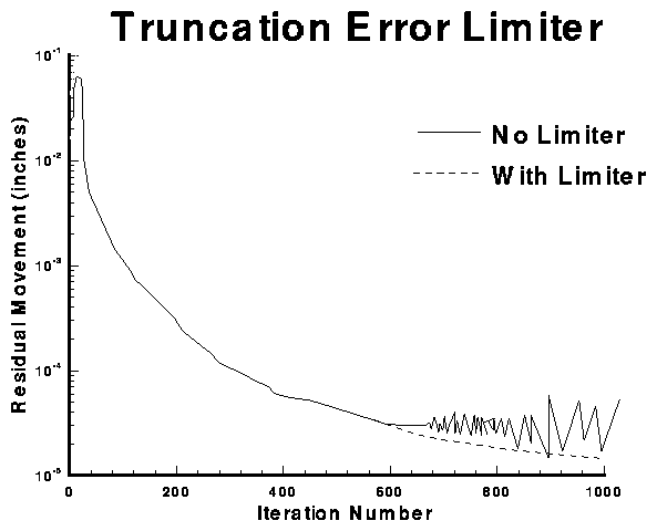
Truncation Error Limiting - As explained before, low precision machines may cause solver divergence if the uncertainty in the update to the elliptic solver orthogonality source terms are not accurate. This usually arises when the source terms have converged, but the grid has not. If the source terms are converged, and the inaccuracy of low precision machines creeps into the updates, the updates to the source terms can magnify and eventually cause solver divergence. To prevent this, the 3DMAGGS code can stop the update to the source terms, while letting the grid converge based on the frozen source terms. Illustrated below are the effects of this controlled convergence:

Truncation Error Limiter Performance


GRIDGEN3D to 3DMAGGS: Since 3DMAGGS was designed to replace GRIDGEN3D, the 3DMAGGS set of support codes provide conversion software to use GRIDGEN3D input data with 3DMAGGS. The conversion software, called PREMAGGS, uses an input deck to control the conversion. The PREMAGGS code is controlled via an input deck, similar to the one illustrated below:

                   ***** PRE 3DMAGGS CONTROL FILE *****
-------------------------------------------------------------------------------
Working directory of 3DMAGGS runs    (a):~/mesh/ssv/c1/3dmaggs/elevon/10/
FLAGS ctd,face,dsi,3dj,3dg,3dv     (6i2): 1 1 1 1 1 1 
UNIX Script file (cray,sgi,onyx)     (a):sgi
Configuration name                   (a):SSV001VIS -> Controls @ 10 degrees
Default file name prefix             (a):elv10-vol
Block Information file (*.bnda)      (a):elv10-vol.bnda
Face Information file (*.mlga)       (a):elv10-vol.mlga
Number of iteration sequences       (i2):03
  Number of    Laplace(0)   Coarse(0)/   Thomas & 
  Iterations   Poisson(1)   Fine(1)      Middlecoff
    100           0            1             0
    300           1            1             0
    600           1            1             3
Relaxation parameter             (f12.6):-.75
Decay rates for each block/face  (f12.6):6.
Block   Face    Decay
Number  Number  Rate
  1       1     -.45
  1       2     0.40
  1       3     0.40
  1       4     0.25
  1       5     0.25
  1       6     0.15
Sorenson init (1); 3DTFI (2)     (f12.6): 2.
Orthogonality Control               (i4): -6
   Block   Face    Interp.   Interp.  Blending  Normalized
  Number  Number  indx1->3  indx2->4  Function  Arc Lengths
     1      1         2         2         3         1
     1      2         1         1         3         1
     1      3         1         1         1         1
     1      4         1         1         1         1
     1      5         1         1         3         1
     1      6         2         2         3         1

The PREMAGGS code generates all the input data decks for 3DMAGGS, generates scripts to control 3DMAGGS based on architecture, redimensions 3DMAGGS and 3DVOLCHK for the proper amount of memory required, and generates the cell heights used in the formulation of orthogonality controls with the Poisson equation solver. This preprocessor significantly reduces the steps to convert GRIDGEN3D input data to the point of running the 3DMAGGS code to develop a volume grid.


NASA Official Responsible for Content --
Stephen J. Alter Last Updated November 6, 2002
Feedback on Langley Products and Services